John Deere 24 Volt Electrical Systems on Electric Start 70, 720, 730,
820 and 830 Diesels
A bit of a background to this info: We purchased a Model 70 Diesel
with pony start. We had to overhaul the main diesel engine and decided
to put an electrical start on the tractor at that time. We purchased an
electric starting system from a junked 730. Everything bolted up fine,
we did need to remove the divider in the battery box on the 70, and
replace the generator bracket along with make a holder plate for the
regulator.
The problem came in when we tried to find accurate knowledge on
wiring and how the electrical system worked. We interviewed a number
of persons who all claimed they "understood" the 24 volt system. Every
time we tried their way, the batteries would drain or there would be some
After months of piecing together info we finally found a man who they
said had been born on a John Deere tractor. His name was Clyde Henry
who had been a serviceman and salesman for an older John Deere dealer.
(Sichi Farm Supply in 84 Pa.)
Clyde filled in the pieces of the puzzle for us and using the info below
we have had almost no problems with the system, other than the normal
battery replacement.
We later purchased a 720 Diesel that came with electric start. It worked
fine, but wasn't wired to our diagram below. We re-wired the system to
our specs and it worked trouble free for years until we sold the tractor.
> That said....what we have put together below is what has worked for us.
That also doesn't mean we are experts or that ours is the only way, but
the info you find here will go a long way in helping explain the ins and outs
of the JohnDeere 24 volt electrical system.
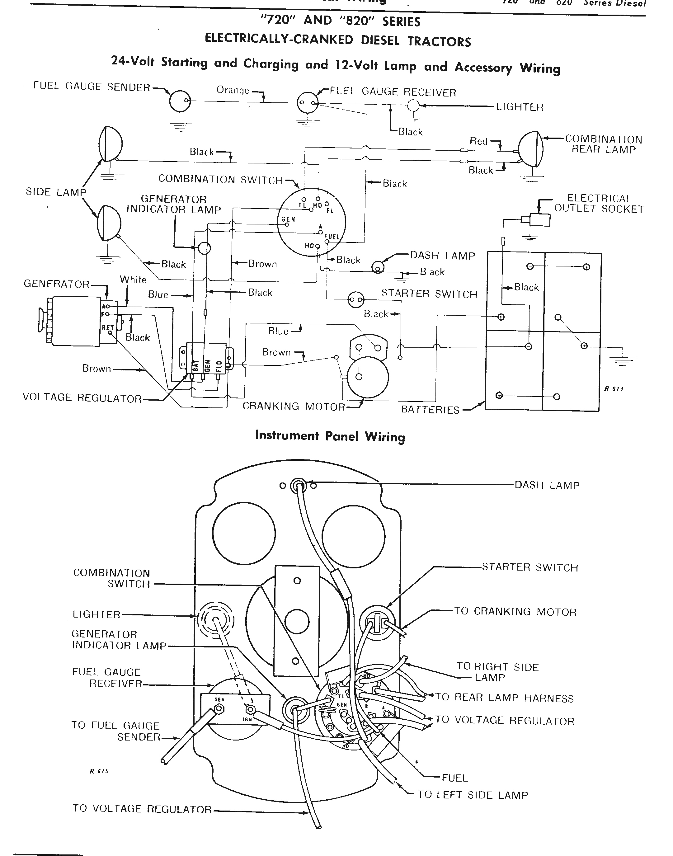
The 24 Volt Electrical System
The electrical system used on John Deere diesel tractors with
electric start is a 24 volt split load system.
Basically there are 3 separate electrical systems within the one main system.
1. 24 volt starting system
2. 12 volt system controlling one side of the tractor
3. 12 volt system controlling the opposite side of the tractor
Take one 12 volt system off the tractor and what is left is a typical 12 volt system.
With this system the difference is the generator brushes are both connected to
the regulator instead of grounding one. The field circuit wire is connected inside
the generator to A 1 terminal. It is the job of the regulator to not only control
voltage or current output, prevent current backflow, but to separate and
distribute the correct amperage to each side of the system.
The 24 volt system must, at all times, have each component isolated from ground!
The return circuit is carried back to the battery by wires instead of
through the frame. The 12 volt system returns voltage through
the frame. Every individual part of the starting motor,
generator, and solenoid is insulated from being
grounded. Brushes, brush holders, field coils, armatures, etc,
are all isolated and insulated from touching ground.
Any ground within the 24 volt system will cause current to
drain from the batteries.
Again: the Entire cranking and charging circuit is carried by
wires...No part of it is grounded to the tractor frame.
Voltage from Battery A controls left hand or flywheel side of tractor.Voltage from Battery B controls right hand side.
The secret to maintaining equal battery strength is to balance the
amperage draw so they are pretty much equal from both batteries. The
50 ohm resistors are provided on the ignition switch to guard against
a sudden surge of voltage or in the event 24 volts should ever arise at that point.
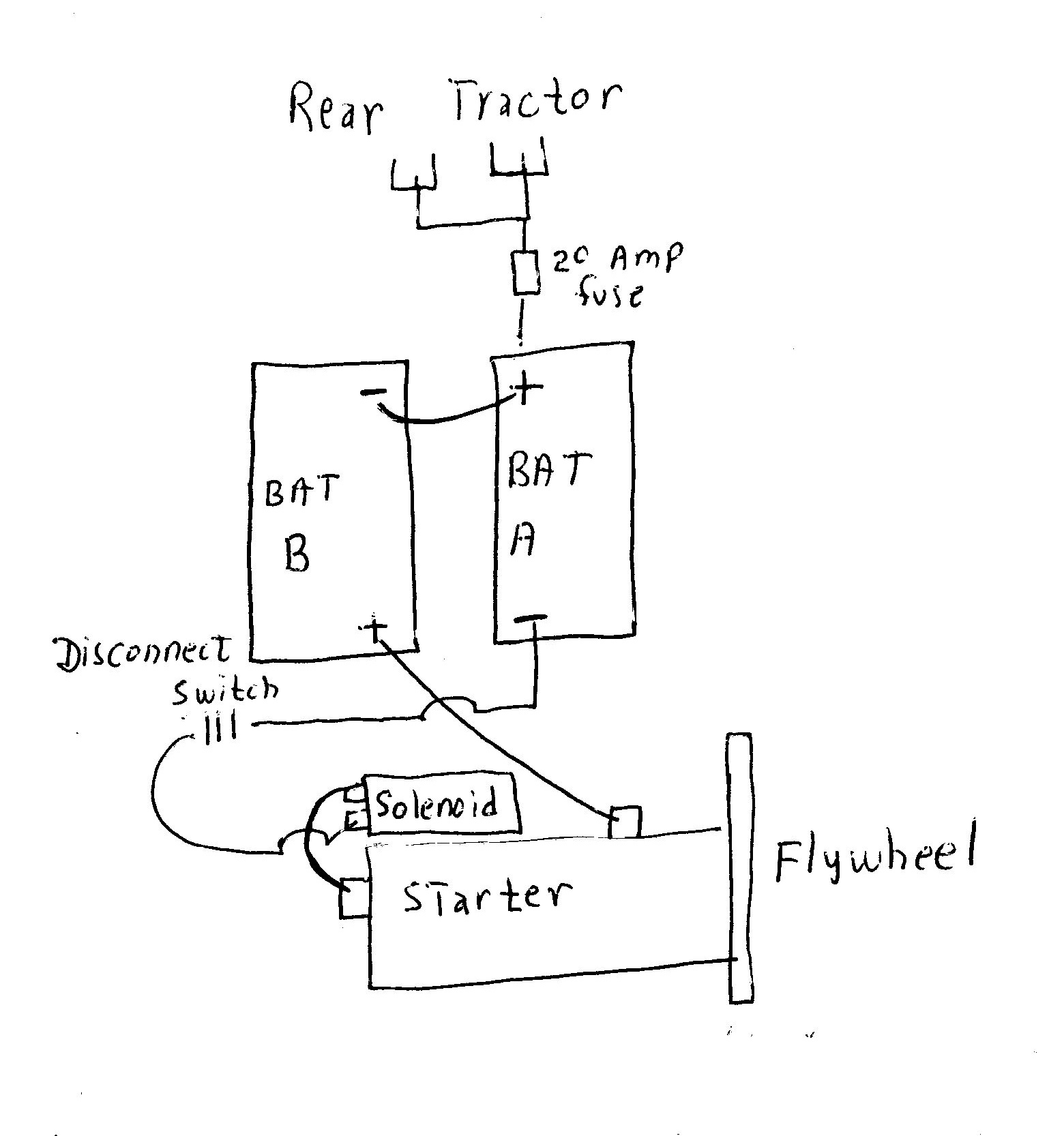
Batteries are hooked in series with a 14 gauge wire connected to the
positive post of Battery A, through a 20 amp fuse, then grounded on
the battery box and to tractor frame. This fuse (not original J.D. wiring)
serves as an additional protection of 12 volt components.
An additional protection that we used is the addition of a master
disconnect switch located in series between Battery A negative post
and the solenoid BAT post. This prevents battery drain or accidental
starting.
===============================================
Hooking the negative post from Battery B and the positive post from
Battery A to two separate frame grounds (as was original J.D. wiring on
the 4010 and some 4020 series) provides little if any safety
factor as has been evidenced by many owners of 4010's and 4020's
who found their tractors suddenly catching fire. As a side note,
many owners of these tractors have also found them to have
somehow been able to start themselves.
In the middle of the 4020 series, Deere returned to hooking the
batteries in series with a small ground wire.
===============================================
When the tractor starts and generator begins to produce electricity,
current flows from A 1 (white wire) to Indicator Light. The Indicator
Light is a reverse flow type of switch which causes the bulb to go out
when current flow is reversed.
The current then goes from A 1 to the voltage regulator ARM terminal,
through the regulator, out the Blue wire to BAT A on Ignition Switch,
to load if needed (lights, etc)
If no load, then current will flow on Blue wire from BAT on Regulator
to solenoid and on to Battery A.
If current is needed for both battery re-charge and load, then it will be
split at junction on Regulator BAT terminal and flow as needed.
Current also flows from Generator A 2 (brown wire) to Ignition Switch
Bat B, then to load and to GND on Regulator, then to solenoid
terminal, through shielded ground wire to starting motor post nearest flywheel
then on to charge Battery B.
Generator produces it's own current to increase magnetism in field
coils, controlled by Black wire from Gen F to Regulator F.
=================================================
Generator output (depending upon state of battery discharge and load)
should be 10 amps. To check:
Disconnect F and A 1 terminals, tape ends to prevent grounding.
Using accurate tachometer, run engine at 1200 rpm.
Connect voltmeter and ammeter in series with carbon pile resistor to
terminals A 1 to A 2.
Connect jumper from F to A 2.
Run engine.
Adjust resistor to obtain 28.5 volts.
Output should be 10 amps.
Re-polarize generator every time any wire in charging circuit is disconnected,
or generator pulley is turned even once with any charging system wire off.
To polarize: Momentarily connect jumper wire from Regulator BAT to
GEN or ARM....Do not touch any grounded surface.
================================================
The least understood aspect of the system is that with Ignition Switch
OFF and tractor Not running....the entire system is "Hot".
If measured with a voltmeter, all points will read 12 volts.
If connected across the two solenoid posts there will be a reading of
24 volts.
If connected between any terminal on the charging system and ground,
there will be 12 volts.
The polarity will not always be the same, it will depend upon which battery
controls the circuit being tested. The voltage is always at each terminal,
however it is electrically neutral, or not flowing.
Grounding any function completes the circuit which then causes current to flow.
When a voltmeter is used what actually happens is one lead is
connected to a frame ground. The electrons in the circuitry then have
a path to flow and current will go from terminal, through meter, to
ground...actually completing the circuit.
However this does not mean the component being tested will operate.
Specifically using any component, say the lights....completes
the circuit to ground and the lights come on.
The Ignition Switch is a combination switch. It is really two switches
in one switch and operated by a single lever. One half the switch controls
current to 1/2 the load (one battery), the other half of the switch controls
current to the remaining battery.
Instead of using the traditional 4, 6 volt batttery hookup that was
factory, we used two 12 volt batteries.
These 12 volt batteries MUST be a Minimum of 1000 CCA!
Trouble Shooting
Regulator cover is Hot at all times....be careful when working around
the regulator.
* A quick check of the starting motor for ground is to disconnect Bat B terminal,
place an ohm meter on starter post nearest flywheel and on tractor frame.
There should be NO reading.
* On the 24 volt system, the solenoid return wire between the solenoid return
terminal and the + terminal on the starting motor is in the hold - in winding circuit.
A bad battery connection will melt the battery post or connection and open
the circuit. An open circuit here would cause the solenoid switch to engage
and then immediately disengage and continue as long as the starting button
is held in. Other possible causes could be a bad battery connection or low battery.
* If water is added to the batteries too frequently voltage regulator setting is too high.
If added to only one battery, there is an unbalanced load or too many amps
being drawn from the battery using more water. Temporary correction can be
made by switching batteries or adding a second outlet socket with a 32
candlepower bulb.
Poor connections are a main source of problems!
All connections absolutely must be kept clean, bright and tight.
* Excessive resistance in the charging circuit results in under charged batteries.
To check: connect ammeter between battery terminal of regulator and the
blue lead removed. Connect jumper lead between generator F and A 2.
Do not touch jumper to any ground, it will reverse polarity.
Turn off all accessories, run engine to produce charge rate of 10 amps. Do
not exceed.
Measure voltage between
1. Generator armature terminal F to a pin connector in negative battery post
0.8 volt max.
2. A 2 to regulator GND 0.1 volt max
3. A 2 to positive terminal of right side battery 0.5 volt max
4. From ground post on left side battery to ground post on right battery 0.1 volt max
5. Disconnect jumper and turn on lights, run engine, obtain 10 amps reading
from generator F to regulator F should not exceed 0.05 volts.
If higher readings are obtained there is high resistance in the circuit. If voltage drop
is under max, connect regulator lead and re-polarize generator.
* Abnormal fluctuation of the ammeter while testing the charging circuit indicates
oxidized regulator points. To test: disconnect blue wire from BAT terminal on regulator
and connect ammeter in series. Start engine, turn on lights, adjust speed until
ammeter reads 8 amps (if battery is charged, it may need to discharge first),
connect jumper wire to generator F and A 2. If ammeter increases more than 2
amps, regulator points are oxidized.
* In the regulator cutout relay, closing range is 24 to 27 volts. Closing voltage
must be 0.5 volt or more below the voltage regulator setting. Setting should be
27.5 to 29.5 at normal operating temperature. The current regulator setting range
is 9.5 to 11.5 amps. If one battery tends to stay lower, set on high side of range.
* To test regulator voltage: disconnect blue wire from BAT terminal.
Make connection: from GND to 7 ohm resistor to BAT terminal.
One side of volt meter on BAT, the other side to GND.
Run engine to operating temperature. Stop and restart engine. At high engine
RPM, volt meter reading should be 27.5 to 29.5 volts. A low voltage regulator
setting will increase the difference in the charged state of batteries.
* Regulator Current: disconnect blue wire to BAT terminal.
Connect an ammeter to the BAT terminal and the other lead to the blue wire.
Connect a volt meter to the BAT terminal and the other lead to GND.
Start engine several times. Run engine at high RPM and turn on lights.
With volt meter reading approximately 1 volt below voltage regulator setting,
ammeter should read 9.5 to 11.5 amps.
* High Resistance Tests:
Pull throttle all the way to rear past stop.
Operate starter and compare readings with below:
G to F 0.2 volt max
B to C 0.2 volt max
C to E 0.2 volt max
A to H 0.1 volt max
C to D 0.1 volt max
Voltage readings that exceed these indicate defective wires or bad connections.
A = right side battery, postive post
B = right side battery, negative post
C = solenoid post nearest front of tractor
D = BAT terminal regulator
E = Solenoid post nearest rear of tractor
F = Post on starter motor connected to battery
* The regulator cutout relay can be adjusted for air gap and point opening.
Airgap: move relay armature toward core until points just close.
Insert feeler gauge (0.017) between armature and core. Raise or lower asrequired making sure points are aligned
Point Opening: Bend armature stop until point opening can be measured
with a 0.032 feeler gauge.
* Voltage and current regulators can only be adjusted for air gap. Push
armature down until points just make contact. Measure gap and adjust as follows:
Regulators:
1119219C, 1119282C, 1119282D, 1119135D setting is 0.75
1119135E, 1118896E voltage regulator gap is 0.060; current regulator
gap is 0.075
=====================================================
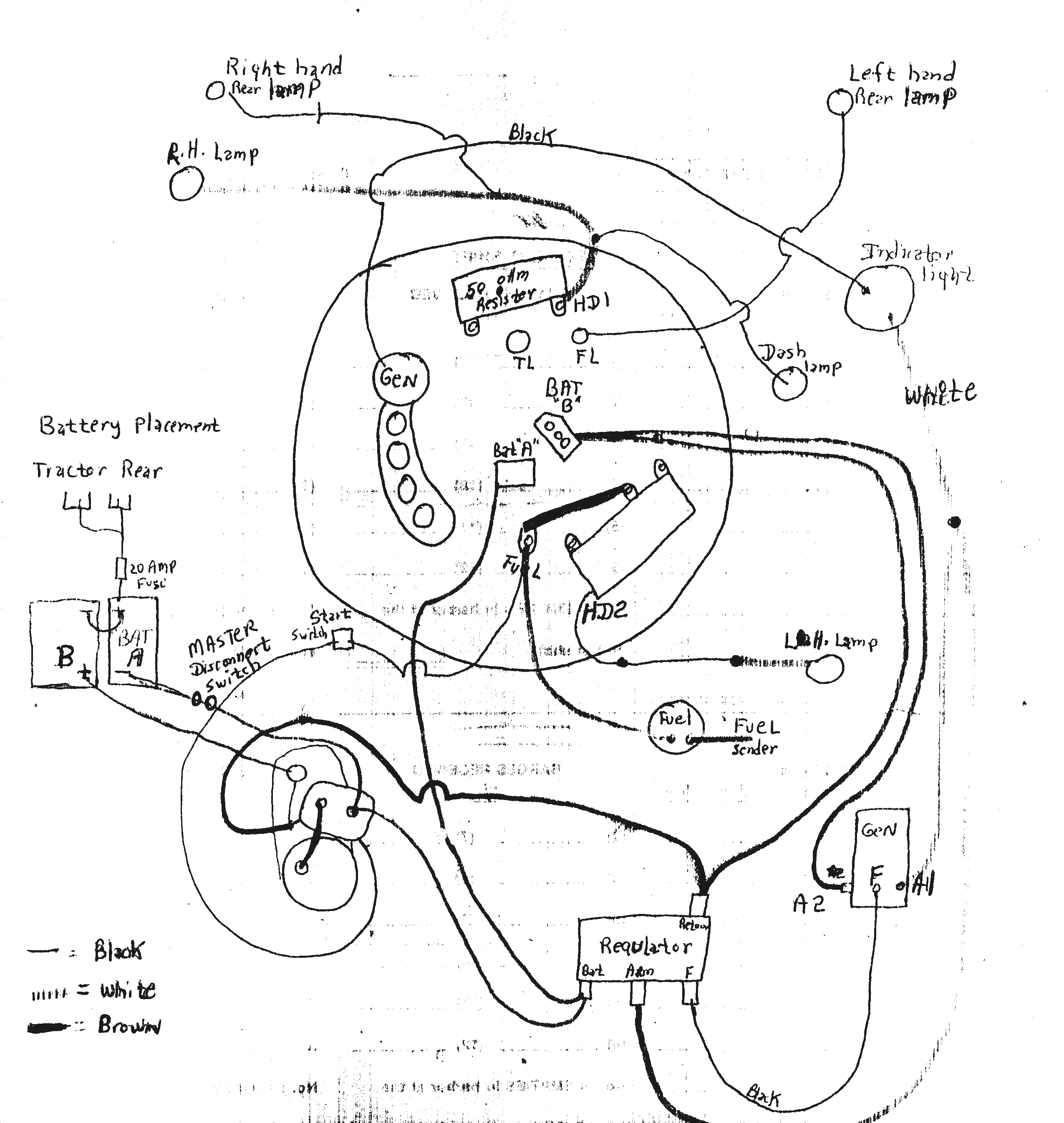
Wiring Diagram
Left Side (flywheel) battery is A
Right side (clutch pulley) battery is B
Battery A positive post to 20 amp fuse to two separate grounds
Battery A positive post to Battery B negative post.
Battery A negative post to starter solenoid terminal nearest front of tractor.
(It is a good idea to connect a master cut out switch in this wire and shut
off master switch after each use)
Battery B positive post to terminal on side of starting motor.
Solenoid post nearest rear side of tractor to post on starting motor terminal
facing the clutch pulley.
Battery Hookup
Our Wiring Diagram
John Deere's Original Wiring Diagram
Back to:
History of John Deere Tractors
Index everything John Deere
 Custom Search
Dave Cole
Choose To Prosper LLC.
Copyright ©